20 MeV 양성자 가속기 제작 및 시험 (RFQ / DTL 공동을 중심으로) 포항공대, 물리학과 2007. 5. 30 권 혁 중 양성자기반공학기술개발사업단 한국원자력연구원 1
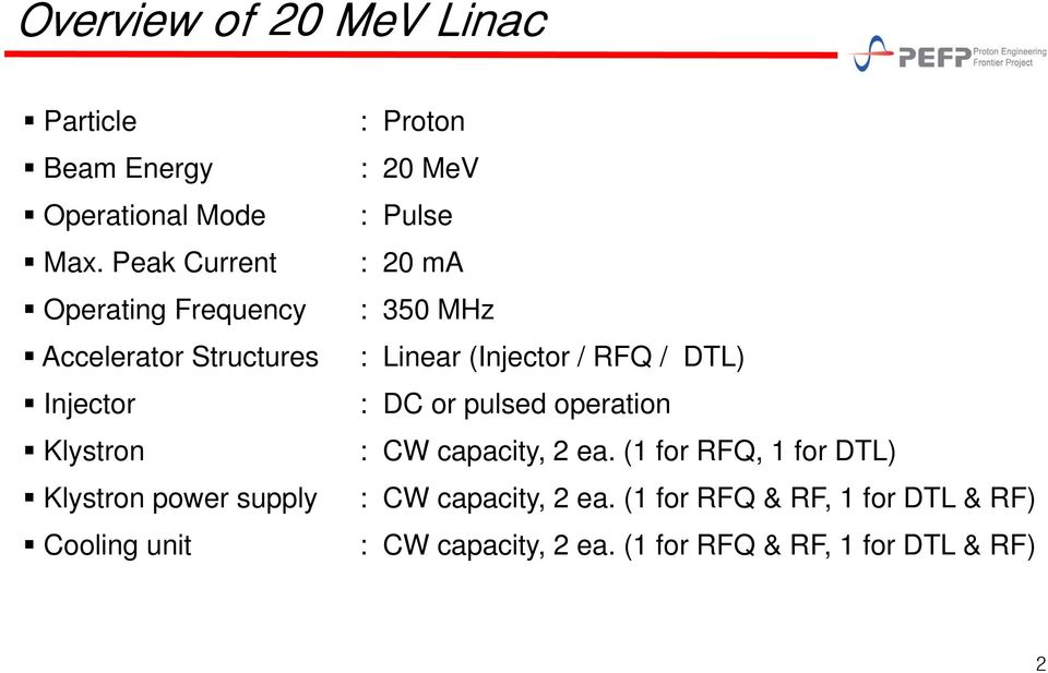
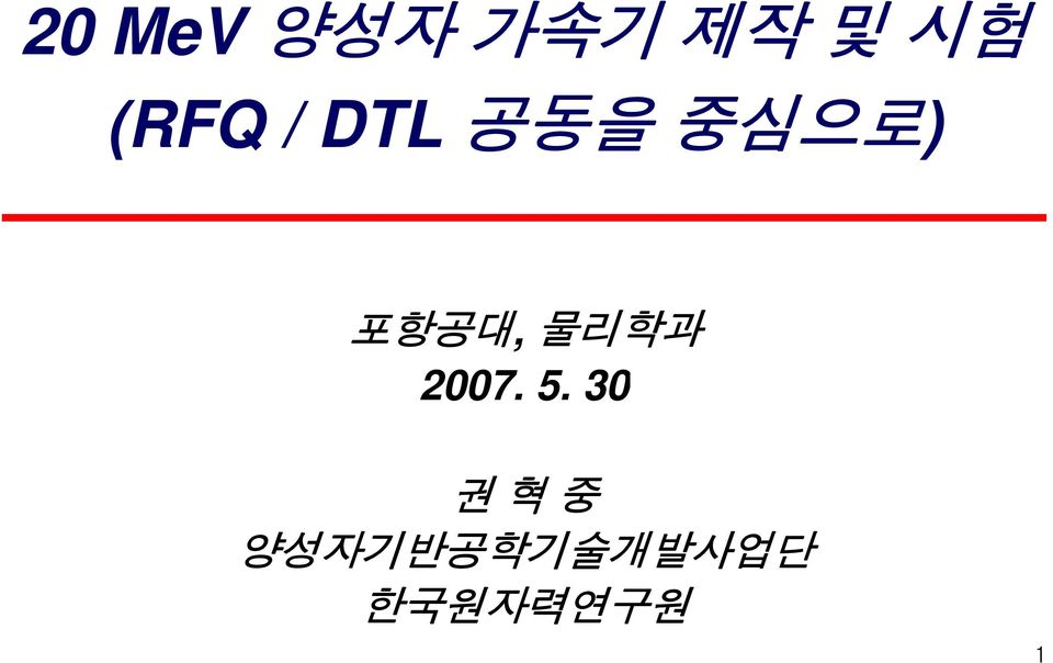
Overview of 20 MeV Linac Particle Beam Energy Operational Mode Max. Peak Current Operating Frequency Accelerator Structures Injector Klystron Klystron power supply Cooling unit : Proton : 20 MeV : Pulse : 20 ma : 350 MHz : Linear (Injector / RFQ / DTL) : DC or pulsed operation : CW capacity, 2 ea. (1 for RFQ, 1 for DTL) : CW capacity, 2 ea. (1 for RFQ & RF, 1 for DTL & RF) : CW capacity, 2 ea. (1 for RFQ & RF, 1 for DTL & RF) 2
20 MeV Proton Linac at KAERI Site Klystron for RFQ 350MHz 1MW CW Waveguide WR2300 Klystron for DTL 350MHz 1MW CW Beam Dump 100kW Proton Injector 50keV 40mA LEBT 2 Solenoids 3MeV RFQ 350MHz 4 Vane Brazed Structuret 20MeV DTL 4 Tank 150 Drift tube Electroplated Tank Pool type Electromagnet 3
PEFP RFQ Parameters Frequency : 350MHz Input / Output Energy : 50keV / 3MeV Peak Beam Current : 20mA Vane Voltage : 85kV (Constant) ρ/r 0 : 0.87 Input emittance :02π 0.2 π mm - mrad (Normalized rms) Output emittance : 0.2 π mm - mrad, 0.112 deg - MeV Transmission rate : 98.3 % RF duty : 24 % Repetition rate : 60 Hz RF power (80% Q) : 460 kw (cu : 400kW, beam : 60kW) Peak surface field Stabilization Total length : 1.8 Kilpatrick : resonant coupling, stabilizer rod : 325 cm 4
PEFP DTL Parameters Tank Tank 1 Tank 2 Tank 3 Tank 4 Energy range (MeV) 3.00 ~ 7.18 7.18 ~ 11.50 11.50 ~ 15.80 15.80 ~ 20.00 Number of cells (ea.) 51 39 33 29 Synchronous phase (deg.) -30-30 -30-30 Quad gradient (kg/cm) 5.0 5.0 5.0 5.0 Effective Quad. Length (cm) 3.5 3.5 3.5 3.5 E0 (MV/m) 1.3 1.3 1.3 1.3 Transit time factor 0.83 0.83~0.81 0.81~0.79 0.79~0.77 Drift tubes (ea.) 50 38 32 28 EMQs (ea.) 52 40 34 30 Post couplers (ea.) 17 19 16 14 Slug tuners (ea.) 8 (±1MHz) 8 (±1MHz) 8 (±1MHz) 8 (±1MHz) Length (cm) 443.1 464.9 475.5 477.6 Diameter (cm) 54.44 54.44 54.44 54.44 Total power (kw) /Cu /Beam 225.0/141.6/83.4 225.0/138.8/86.2 224.0/138.3/ 85.7 221.0/ 137.1/ 83.9 5
Stan Schriber (LANL / CERN) Design, Analysis, Construction, Assembly, Tuning, Installation, Commissioning and Operation (DACATICO). Everything learned in past 35 years 자료 중간에 나타나 있는 페이지는 T. P. Wangler 책 페이지 임 6
Construction, Assembly 설계 온도, 가공 온도 중요 가공 치수 온도 보정 가공 공차 튜너 보정 가능 범위내에서 허용 공차 설정 정렬 오차 빔 동력학 오차 해석 결과로부터 허용 오차 설정 7
DTL Cavity (DTL Tank - p.95) Stem Drift tube Accelerating gap cell 1 cell 1 cell 길이, 인접 gap 사이 거리 - βλ : cell 길이가각각다름 1 cell 형태 : nose를 가진 실린더 형태 공동 : 높은 가속 효율 각 cell 전장 위상은 동일 : zero 모드 빔 집속용 사극 자석은 DT (Drift Tube) 내에 설치 각 cell 구조 : SUPERFISH 코드의 DTLFISH 모듈 이용 8
DTL Cavity (DTL Tank) 설계 20MeV DTL - Tank : 4ea - 1 Tank : 2 sections - Tank Length : 4.5m/ea - Lattice : FFDD - Total RF : 900kW DTL Quadrupole Magnet 35 35 30 30 25 25 20 20 15 15 10 10 5 5 Beam Optics 0 0 KOMAC Drift-Tube Linac F = 349.99982 MHz 0 5 10 15 20 25 30 35 40 45 50 55 Magnet 25 20 Stem Post 15 10 Drift Tube Power coupler port 5 0 0 5 10 Drift Tube Cavity 9
DTL Cavity (DTL Tank) 제작 1 Tank : 2 section (Tank 1 - 직경 : 54.44 cm, 길이 : 443.1cm) 제작: Steel pipe 내에구리도금 (100 um 도금-> 50 um 가공) Power coupler coupler port (1개 / 탱크 ) Stem port ( 탱크 1 : 50개) 간격 온도 보정 Pick up port Wall cooling channel (18 개 / 단면) Post coupler port (1개 / DT2 개, 3개) Vacuum port (4개 / 탱크) Slug tuner port (8개 / 탱크) 10
사극 전자석 제작 Max. GL = 20 kg/cm * cm Type : Pool type electromagnet (IPHI DTL, CEA) non hollow conductor coil single cooling circuit for DT & magnet coaxial stem Aperture : 20mm diameter Good Field (1%) : 14mm diameter Multi-Pole : < 1% (Min. Multi-Pole Face) CoreOuterDiameter:110mm Length : 30mm Coil : 3mmx3mm No. of turns : 8 Max. Current : 2,200 AT Joule dissipation i : 800W 11
Drift Tube 제작 재료 : 무산소동 탱크 1번 DT 개수 :50 (20M MeV VDTL총 DT 개수 :148개) DT 직경 : 내경 14 mm, 외경 130 mm Stem 직경 : 26mm (coaxial cooling channel) 가공 공차: 전자빔 용접 : DT body to cap cover 브레이징 접합 : DT to stem 1. 부품 가공 및 브레이징 접합 2. 전자석 설치 3. 전자빔 용접 12
Drift Tube 설치 및 정렬 설치 : Stem mount (DT 홀더 + DT 위치 및 방향 조절) 정렬 : Laser Tracker 이용 정렬 허용 오차 : Transverse : <± 50 um, longitudinal : <± 50 um, tilt angle : < 1 온도 보정 Target mount on DT Stem mount Laser Tracker Data Acquisition 13
Drift Tube 정렬 결과 Y Position [mic crometer] 50 Tank 01 0-50 -50 0 50 X Position [micrometer] Y position [m micrometer] 50 Tank 02 0-50 -50 0 50 X position [micrometer] r] itin [micrometer Y posi 50 Tank 03 0-50 -50 0 50 X position [micrometer] ter] Y pos sition [micromet 50 0 Tank 04-50 -50 0 50 X position [micrometer] 네 개 탱크의 DT 정렬 결과 정렬 된 Drift Tube 실 - 무슨 용도 (?) 14
RFQ Cavity (p.225) 빔 진행 방향과 수직 방향 : 전장에 의한 빔 집속 (FODO) 빔진행방향: 빔의가속및번칭(기본셀구조: 0.5 βλ ) 각셀전장위상은pi mode 인단일공동: 공동기준zero 모드 15
RFQ Cavity 설계 r0 및 a 는 가속 효율 및 빔 정합에 의하여 결정 빔 진행 방향 베인 가공 치수 : PARMTEQ 코드의 Vanes 모듈 이용 빔 진행 수직 방향 cavity 단면 가공 치수 : SUPERFISH 코드 RFQFISH 모듈 이용 16
RFQ Cavity 설계 Vacuum port ( 4 ea.) RF coupler port ( 2 ea.) Vacuum port ( 4 ea.) LE side HE side Tuner port ( 52 ea.) Section (length : ~ 0.8m) Segment Coupling plate Coolant port ( 12 ea./section) 17
RFQ Cavity 제작 1. 베인 가공 (minor vane 2sets + major vane 2sets) Vanes 출력 데이터를 NC 머신 가공 데이터로 변환 가공 공차 : ~ 20 um 가공 치수 온도 보정 가공시 주위 온도 안정화 2. 베인 정렬 브레이징 접합 전베인 정렬 정렬 방법 : 공진 주파수 및 각 quadrant 장 분포 크기 측정 결과로 결정 공진 주파수 측정시 온도 보정 정렬시 주위 온도 안정화 18
RFQ Cavity 제작 Tuner & pick up ports Vacuum port 3. 세척 4. 브레이징 접합 접합재 BAg-8 (Ag : 70, Cu : 30) 접합 온도 :850도 (12시간 +20분 +12 시간) 5. 진공도 확인 헬륨 누설 누설률 기준 : 1 10-9 torr L/s 이하 19
튜닝 가공 및 정렬 오차 보정, 외부 섭동에 의한 장 분포 안정화 가 목적 내용 공진 주파수 장분포 장분포안정화 고주파 결합기 결합 계수 조절 튜닝시 cavity 온도를 포함한 주위 환경 안정화 필수 20
목표 주파수 설정 고려 사항 : 진공, 습도, 온도 운전 조건: 350 MHz, 진공, 35 튜닝 조건: 대기압, 27 349.92 Reson ant Frequency in Air [MHz z] 349.91 349.90 349.89 349.88 349.87 349.86 349.85 0 20 40 60 80 100 Relative Humidity [%] 21
장 분포 측정 방법 (p.162) Step motor driven pulley DTL tank Monofilament fishing line Bead Drift tube RF pickup RF pickup Step motor/ Network PC/ Motor controller Analyzer LabVIEW Slater s perturbation theorem Δ ω 0 3ΔV ε r 1 1 E μ = ε + μ H ω0 4U εr + 2 μ + 2 2 r 2 0 0 r tan Ψ = 2 Q L δ, where δ = ω ω0 ω ω 0 Measure S21 phase shift due to perturbation 22
Multi cell cavity의 장 분포 특징 (p.247) DTL 공동을 전송선으로 근사한 모델에 섭동 이론 적용 ΔE E 0 Δω ω 0 0 2 ( v ) 0 l λ 경우 1 (sum 1) : P1~P8 (+ Δω) 경우 2(sum2): 2) P1~P4 P4 (+ Δω), P5~P8 P8 (- Δω) 0.01 P1 P2 P3 P4 P5 P6 P7 P8 sum1 sum2 0.04 P1 P2 P3 P4 P5 P6 P7 P8 sum1 sum2 0.005 0.02 DeltaE0/E0 0 DeltaE0/E0 0-0.005-0.02-0.01 0 0.2 0.4 0.6 0.8 1 P1 Length (x/l) P8 공진 주파수 오차 : 8 Δω, 전장 분포 오차 : ~ flat -0.04 0 02 0.2 04 0.4 06 0.6 08 0.8 1 Length (x/l) 23 공진 주파수 오차 : 0, 전장 분포 오차 : ~ Tilt
Multi cell cavity의 장 분포 안정화 (p.103) π/2 mode are very insensitive to small frequency errors the field distribution for zero and π modes can be sensitive to resonant frequency errors then, zero mode RFQ and DTL? 1. Create another lower passband 2. Join the two passbands : Confluence 24
Multi cell cavity의 장 분포 안정화 - DTL의 경우 Post coupler 를 설치하여, 기존 가속 mode (upper passbands)와 post coupler mode (lower passbands)를 confluence 시킴 (p. 100) Cavity mode Cavity mode Post mode uency [MHz] freq 375 370 365 360 355 350 345 frequ uency [MHz] 375 370 365 360 355 350 345 340 0 1 2 3 4 5 340 0 1 2 3 4 5 mode number mode number Dispersion without post coupler Dispersion with post coupler 25
Multi cell cavity의 장 분포 안정화 - RFQ의 경우 Dipole mode : pi mode stabilizer, dipole stabilizer rods, vane coupling ring 등 Quadrupole mode : coupling plate 등을 이용하여 운전 모드로 부터 상하모드간격을같도록맞추어줌 Vane Coupling Ring Pi Mode Stabilizing i Loop Dipole Stabilizing i Rod, (LBNL) (J-Parc, SNS) Coupling plate 26 (APT, PEFP)
Cavity 온도 안정화 방법 1kW히터 + 열 차폐재 (보온재) 공진 주파수의 온도 민감도 (DTL 탱크 1번 경우) ~ 5 khz / 도 공진 주파수 안정도 ~ ± 0.5 khz (온도제어~ ± 0.1 도에 해당) 27
튜닝 조건 항목 RFQ DTL 비고 공진 주파수 350.000MHz ± 5 khz 350.000MHz ± 5 khz 대기중 permittivity 효과 보정 튜닝 온도 보정 습도 효과 보정 (튜닝 주파수 ~ 349.9** MHz) 장분포 사극장분포: ± 2 % 이내 분포 :Q의 5%이내 장분포: ± 2 % 이내 RFQ - 52 개 슬러그 튜너 이극 장 ± DTL - 탱크당 8개 슬러그 튜너 외부 섭동에 대한 사극 모드 간격 조절 Tilt sensitivity : RFQ - coupling plate, dipole rods 장 분포 안정화 이극 모드 간격 조절 100 % / MHz DTL - post couplers 28
PEFP DTL 내부 post coupler vacuum grill slug tuner fishing line 29
DTL 장 분포 측정 180 175 phase [degree] S21 170 165 160 155 150 145 140 0 0.1 0.2 0.3 0.4 0.5 0.6 0.7 0.8 0.9 1 normalized distance Measured the phase shift raw data 90 1.04 60 1.03 phase [de egree] 30 0-30 -60 normalized field 1.02 1.01 1.00 0.99 0.98-90 349.84 349.86 349.88 349.9 349.92 349.94 349.96 349.98 350 0.97 0.96 frequency [MHz] 1 6 11 16 21 26 Curve for converting the phase to frequency shift cell number 30
DTL 튜닝 전, 후 장 분포 initial final initial final 1.20 1.20 115 1.15 115 1.15 norma alized field. 1.10 1.05 1.00 0.95 0.90 0.85 0.80 1 11 21 31 41 51 cell number tank1 norm malized field. 1.10 1.05 1.00 095 0.95 0.90 0.85 0.80 1 6 11 16 21 26 31 36 cell number tank2 initial final initial final 120 1.20 120 1.20 1.15 1.15 normalize ed field 1.10 1.05 1.00 0.95 0.90 0.85 normalize ed field 1.10 1.05 1.00 0.95 0.90 0.85 0.80 1 6 11 16 21 26 31 cell number tank3 0.80 1 6 11 16 21 26 cell number tank4 31
DTL 장 분포 안정화 -스펙트럼 32
DTL 튜닝 전, 후의 장 분포 안정화 unperturbed perturbed unperturbed perturbed normaliz zed field 1.1 108 1.08 1.06 1.04 1.02 1 0.98 0.96 0.94 0.92 1 11 21 31 41 51 cell number Before post coupler adjustment normaliz zed field 1.1 108 1.08 1.06 1.04 1.02 1 0.98 0.96 0.94 0.92 1 11 21 31 41 51 cell number After post coupler adjustment Perturbation -first slug: -10 khz -last slug: +10 khz tilt sensitivity Eper Eunper 1 = E Δf unper Spectrum before and after stabilization 33
RFQ 장 분포 측정 - Bead pull setup Bead : hollow ball (diameter : 6.35mm, mass : 0.14g) Measured parameter : phase shift Continuous field profile 050519_1 Measured Q Target Q Error Norm malized field 1.2 1 0.8 0.6 0.4 0.2 6 4 2 0-2 -4 Field error (%) 0-6 0 0.2 0.4 0.6 0.8 1 Normalized distance 34
Stabilizer rods, coupling plate Thickness of the coupling plate Radius of the coupling hole Coupling gap distance Dipole stabilizer rods Coupling plate between section 2 and 3 35
RFQ 튜닝 전, 후의 장 분포 스펙트럼 (p.247) - Coupling plate thickness : 16mm - Coupling plate hole diameter : 118mm - Dipole stabilizer rod length : LE : 145mm, HE : 105mm D0-PI D0-PI D0-0 Q0-PI D0-PI Q0-0 D1-PI Q1-0 D1-PI D1-PI D1-0 Q1-PI D0-PI D0-PI D0-PI D0-0 Q0-PI Q0-0 D1-0 D1-PI D1-PI Q1-PI D1-PI Q1-0 Before tuning After tuning 36
RFQ 튜닝 전, 후의 장 분포 Normalize ed field 050612_14 Measured Q Target Q Error 1.2 6 1 4 0.8 2 0.6 0 0.4-2 0.2-4 0-6 0 0.2 0.4 0.6 0.8 1 Normalized distance 050705_1 Measured ed Q Target agetq Error 1.2 6 Field erro ror (%) 0.1 Initial state - Frequency : 349.817 MHz - Q field : < ± 3% - D field : < ± 10% of Q Final state - Frequency : 349.931 MHz - Q field : < ± 2% - D field : < ± 5% of Q 050705_1 D1 D2 Normalized field 1 08 0.8 0.6 0.4 02 0.2 3 0-3 Field error (%) Field (D/Q Q) 0.05 0-0.05 0-6 -0.1 0 0.2 0.4 0.6 0.8 1 0 0.2 0.4 0.6 0.8 1 Normalized distance Normalized distance 37
고주파 결합기 결합 계수 결정 (p. 304) β o =1+ P P b P c Optimum coupling coefficient, P b is beam power, P c is copper loss. g b c Required Generator Power and Reflected Power (for DTL tank) required generator power, Pg [kw] reflected power (w/ beam), Pr [W] 228.5 3000 228.0 227.5 227.0 226.5 226.0 225.5 2500 2000 1500 1000 500 225.0 0 1.30 1.40 1.50 1.60 1.70 1.80 Coupling Beta 38
결합 계수에 따른 고주파 반사파형 1.2 1 Input RF pulse Prad/Pin 0.8 0.6 Reflected RF power 0.4 Prad/Pin 0.2 0 1.2 1 0.8 0.6 0 10 20 30 40 50 60 70 80 90 100 time [usec] Under coupled case Beta: 0.6 Before Turn off P P rad in = 1 ( 1+ β ) 2 1 2 exp β + β ω0 t 2Q L 2 0.4 02 0.2 0 0 10 20 30 40 50 60 70 80 90 100 time [usec] Critically coupled case Beta: 1.0 Prad/Pin 1.6 1.4 1.2 1 0.8 0.6 0.4 0.2 0 0 10 20 30 40 50 60 70 80 90 100 time [usec] After Turn off P P rad in Over coupled case Beta: 1.6 2 4β ω 0 = exp ( t t ) ( ) 2 off 1+ β QL 39
고주파 결합기 결합 계수 조절 예 (www.jpaw.com) 초기 aperture 크기 결합계수 조절후 aperture 크기 40
Iris coupler Iris type RF coupler with ridge-loaded waveguide coupler - less multipacting - small perturbation to the DTL tank Coupling iris geometry 41
DTL Iris 결합 계수 조절 Analytical formula MicroWave Studio Measurement ling coeff ficienet Coup 1.8 1.6 1.4 1.2 1.0 0.8 0.6 0.4 02 0.2 0.0 2 4 6 8 10 12 14 16 Coupling hole diameter [mm] 42
고주파 제어 운전중 외부 섭동에 대해서 고주파 변수를 일정하게 유지하는 것이 목적 섭동 원인 : Cavity 공진 주파수 변화, 클라이스트론 전원 리플, 빔 로딩 제어 대상 Cavity 내의 고주파 전장 크기 (1% 이내) Cavity 내의 고주파 전장 위상 (1도 이내) Cavity 공진 주파수 (~ BW의 10 %) 43
섭동 원인 - Cavity 공진 주파수 변화 (1). 초기 공진 주파수 = RF 주파수 (2). 변화후 공진 주파수 (3). 고주파 전장 크기 및 위상 보상을 위한 곡선 고주파 전장 크기 고주파 전장 위상 PEFP DTL 탱크 1의 경우 QL ~ 16,000, 공진 주파수가 2.1 khz 벗어났을 경우 - 고주파 전장 크기 : ~ 98 %, 고주파 전장 위상 : ~11도 벗어남 44
섭동 원인 - 클라이스트론 고전압 전원 리플 클라이스트론 특성값 빔 전압과 전자총으로부터 출력 공동까지의 거리 및 운전 주파수로 부터 결정 PEFP TH2089F 클라이스트론의 경우 출력 고주파 전력 : 0.1dB / % 출력 고주파 위상 : 10도 / % 1150 0 Output Power [kw] 1100 1050 1000 950 900 850 800 86 87 88 89 90 91 92 93 94 Vk [kv] 전압 변화에 따른 고주파 전력 변화 phase [deg g] -10-20 -30-40 -50-60 -70 86 87 88 89 90 91 92 93 94 Vk [kv] 전압 변화에 따른 고주파 위상 변화 45
고주파 제어 블록 다이어그램 (p. 152) 고주파 라인 공진 주파수 제어 신호 라인 - 공진 주파수 제어 루프 입력 신호 (공진주파수 에러) Controller RF SSA Klystron controller - 고주파 전장 크기 및 위상 제어 루프 아나로그 : VVA, phase shifter 디지털 : I/Q 모듈레이터 Actuator 방법 1 : Movable tuner (J-PARC) 방법 2:냉각수 온도 조절 (SNS, PEFP) DTL Tank 46
PEFP 고주파 제어 시스템 가속 전장 크기 제어 범위 : 1 % 이내 가속 전장 위상 제어 범위 : 1 도 이내 제어 방식 : Feedback + Feed-forward Feedback 제어기 : PI (Proportional + Integral) 제어기 방식 : 디지털 하드웨어 블록 다이어그램 제어 소프트 웨어 블록 다이어그램 47
HPRF 고주파 제어 시스템 실험 결과 - 안정도 RF pulse width / repetition rate / peak power : 200μs / 0.1 Hz / ~ 150 kw per tank Control gain value (I set / Q set / Pgain / I gain) : 26,000 / 0 / 1.0 / 70,000 RF stability (error in amplitude / error in phase) : < 0.08% / 0.12 degree amplitude measurement 26040 26030 26020 RF power profile 150 kw / tank ch1 : klystron forward, ch2 : tank1, ch3 : tank2, ch4 : tank3 amplitude 26010 26000 25990 25980 25970 25960 0 50 100 150 200 250 300 350 400 shot number Pulse to pulse RF amplitude variation phase measurement Reflected RF power profile 150 kw / tank ch1 : tank1, ch2 : tank2, ch3 : tank3, ch4 : tank4) Over-coupling due to beam loading (coupling beta : 1.6) phase [deg.] 0.20 0.15 0.10 0.05 0.00-0.05-0.10-0.15 015-0.20 0 50 100 150 200 250 300 350 400 shot number Pulse to pulse RF phase variation 48
Feed-Forward Forward 로직 적용 - LLRF 실험 OPEN LOOP 기존에 사용하던 이득값 (P gain: 0.64, I gain: 230000) 계산에 의한 이득값 (P gain: 0.53, I gain: 285000) Yellow: forward RF power Blue: upper half of 10 MHz IF signal Feedforward Only Feedback and Feedforward 49
빔 가속 시험 각 장치의 운전 변수값을 찾는 것이 목적 : 초기 빔 전류 1mA 로 제한 운전 변수 튜닝 : 현재는 빔 전달률을 기준으로 결정 이온원 전압 운전값 LEBT 솔레노이드, 스티어링 전자석 운전값 RFQ 고주파 전력 DTL 고주파 전력 DTL 탱크 스티어링 RFQ - DTL 사이의 고주파 위상 50
High Power RF Test - RFQ Forward power : 450kW, 80us, 1Hz Peak surface field : ~1.8 18Kilpatrick ti Coupling beta : ~ 0.62 ( 6 mm diameter hole, target : 1.15) Conditioning time to reach peak power : ~ 8 hrs Sparking rate : ~ 1 / 400 pulses Ch 1 : Forward Ch 2 : reverse Ch 3 : cavity Ch 4 : klystron rev. 전형적인 under coupling 반사파형 Electron loading during conditioning (reverse power increase & vacuum degradation) Full power after 8 hrs from starting conditioning 51
LEBT 변수에 따른 RFQ 출구 빔 전류 Sol#1 (Sol#2=120A) Sol#2 (Sol#1=84A) str#1 (x) - str#2 = 0 A str#2 (y) - str#1 = 0.35 A RF FQ output cur rrent [A.U.] 1.6 1.4 1.2 1 0.8 0.6 0.4 0.2 0 60 80 100 120 140 LEBT solenoid current [A] RFQ output beam current depending on solenoid magnets RFQ beam cur rrent [A.U.] 1.4 1.2 1 0.8 0.6 0.4 0.2 0-0.3-0.1 0.1 0.3 0.5 0.7 0.9 LEBT steering magnet current [A] RFQ output beam current depending on steering magnets 52
RFQ 고주파 전력 운전값 결정 고주파전력값에대한빔전달률을측정하여이것을계산값과비교하여결정 Norm malized bea am current 1.2 1 0.8 0.6 0.4 0.2 Measured data PARMTEQ data PARMTEQ100keV Measured beam current Accelerated beam current Total beam current 0 0 0.2 0.4 0.6 0.8 1 1.2 Normalized voltage 53
High Power RF Test - DTL Forward power : 150kW / tank, 80us, 1Hz Couplingbeta: ~ 1.6 16 Conditioning time to reach peak power : ~ 2 hrs Tank 1 : full power reflection rate ~ 1 / 100 pulses Forward power toward each tank cavity field (for 70 us pulse) 54
DTL 탱크 운전 조건 Inlet coolant temp. of DT : 36.8 C (adjusted during test) Tank 1 wall temp. : 21.5 CC Tank 2 wall temp. : 28.4 C Tank 3 wall temp. : 34.7 C Tank 4 wall temp. : 49.2 C Inlet coolant pressure of DT : 5.4 kg/cm2 Resonant frequency differences between tanks : < ± 1 khz 전형적인 over coupling 반사파형 reverse power from each tank 55
이미지를 표시할 수 없습니다. 컴퓨터 메모리가 부족하여 이미지를 열 수 없거나 이미지가 손상되었습니다. 컴퓨터를 다시 시작한 후 파일을 다시 여십시오. 여전히 빨간색 x가 나타나면 이미지를 삭제한 다음 다시 삽입해야 합니다. 20 MeV 시험시 고주파 제어 변수 RF Amplitude adjustment of RFQ and DTL Signal Generator RF phase adjustment between RFQ and DTL Solid State Amp. RFQ Klystron Phase Shifter Solid State Amp. Preset the mechanical phase shifter before test DTL Klystron MPS MPS MPS MPS RFQ TANK1 TANK2 TANK3 TANK4 RFQ field TANK1 field TANK2 field TANK3 field TANK4 field 56
빔 진단 장비 No empty space inside a tank : no steering magnet, no beam diagnostic device inside a tank Current transformer : 5 ea. Faraday cup : 1 ea. BPM : 2 ea. Ion Source LEBT RFQ Tank 1 Tank 2 Tank 3 Tank 4 Beam Dump ACCT FCT TCT TCT BPM 2sets Faraday Cup FCT 57
초기 빔 시험 결과 Parameter adjustment - tank steering, rf phase toward each tank, LEBT parameters Beam transmission through DTL : 100 % (not stable) Beam transmission depending on tuning parameters - tank steering : tank1 LE, HE side : - 1.0mm (x) : tank2 LE, HE side : - 0.5mm (x) : other tanks : 0mm - mechanical phase shifter : all tank phase < ± 10 deg CT1 CT2 CT3 Faraday cup Before tuning 100% 56.7% 42.3% 29.3% tank steering 100% 95.3% 76.0% 20.8% phase shifter 100% 93.9% 77.4% 63.1% LEBT magnet 100% - - ~100% 58
20 MeV 가속기 시험 현재 상태 20 MeV 가속기 시설 검사 완료 ; 방사선 발생 장치 사용 허가 빔전류를높이는시험중 RFQ 출구 첨두 빔 전류 : ~ 5mA DTL 출구 첨두 빔 전류 : ~ 2mA 높은 전류에서 안정된 빔 파형을 얻기 위한 장치 튜닝 중 RFQ 출구 빔 전류 (5mA) DTL 출구 빔 전류 (2mA) 59